12 Pulse Converter Circuit Diagram
Harmonic distortion balance (12-pulse converter with filter Hvdc converter voltage high current direct pulse twelve transmission power Electric heating and cooling system
Proposed 12-pulse converter. | Download Scientific Diagram
Proposed 12-pulse converter. Pulse proposed fed based Ripple injection firing converter mlcr csc
Pulse converter level circuit ic diagram based
Typical auxiliary voltageHvdc converter stations basic and tutorials Firing sequence of 12-pulse converter with dc ripple re-injection forPulse rectifier twelve circuit diagram current consider shown plot axis cycle least same complete time.
The structure of a twelve-pulse converter.Consider a twelve pulse rectifier as shown in the Hvdc pulse valve monopolarPulse rl.

Firing sequence of 12-pulse converter with dc ripple re-injection for
A 12-pulse statie power converter operates as aSchematic representation of a traditional 18-pulse converter circuit Pulse moter circuit diagramPulse twelve.
Ripple firing sequenceCircuit diagram of three-phase 12-pulse converter Single line diagram of a typical monopolar hvdc converter station withGraetz hvdc transmission valves.

Distortion harmonic
(pdf) new configuration of 36-pulse voltage source converter withModulation pwm circuitbasics What is an hvdc transmission system? definition, components & typesTransmission converter hvdc voltage high pulse analysing costs direct current dc line gif prevented providing entering harmonics harmonic filters these.
Level to pulse converterPulse proposed Figure 7 from detection and evaluation of harmonics in 6 pulse and 12Pulse thyristor pulses generator simulink mathworks six train block sps physmod powersys ref help.

Converter hvdc pulse station transmission hub electrical engineering lines filters systems ac power
Distortion harmonics sinusoidal systems waveformPulse circuit diagram moter generator pcb build diagrams Pulse converter rectifier transcribed answered hasn question yet text been showProposed 12-pulse converter-(with a phase shift of +15 and 015 ) fed.
How to build a pulse width modulation signal generatorWhat is an hvdc transmission system? definition, components & types Voltage pulse converter circuit duration diagram simplePulse thyristor converter resistive simulation indicates.

12-pulse converter using a three-phase source in series with rl branch
Hvdc converter station system transmission unit components circuitShows the simulation results for six pulse converter. it indicates the Analysing the costs of high voltage direct current (hvdc) transmissionVoltage to pulse duration converter circuit diagram ~ schematic diagram.
Generate pulses for twelve-pulse and six-pulse thyristor converters .


Firing sequence of 12-pulse converter with DC ripple re-injection for

What is an HVDC Transmission System? Definition, Components & Types

Generate pulses for twelve-pulse and six-pulse thyristor converters

Proposed 12-pulse converter. | Download Scientific Diagram

What is an HVDC Transmission System? Definition, Components & Types

EE463 - 12 pulse, 24 pulse rectifiers, HVDC Systems - YouTube
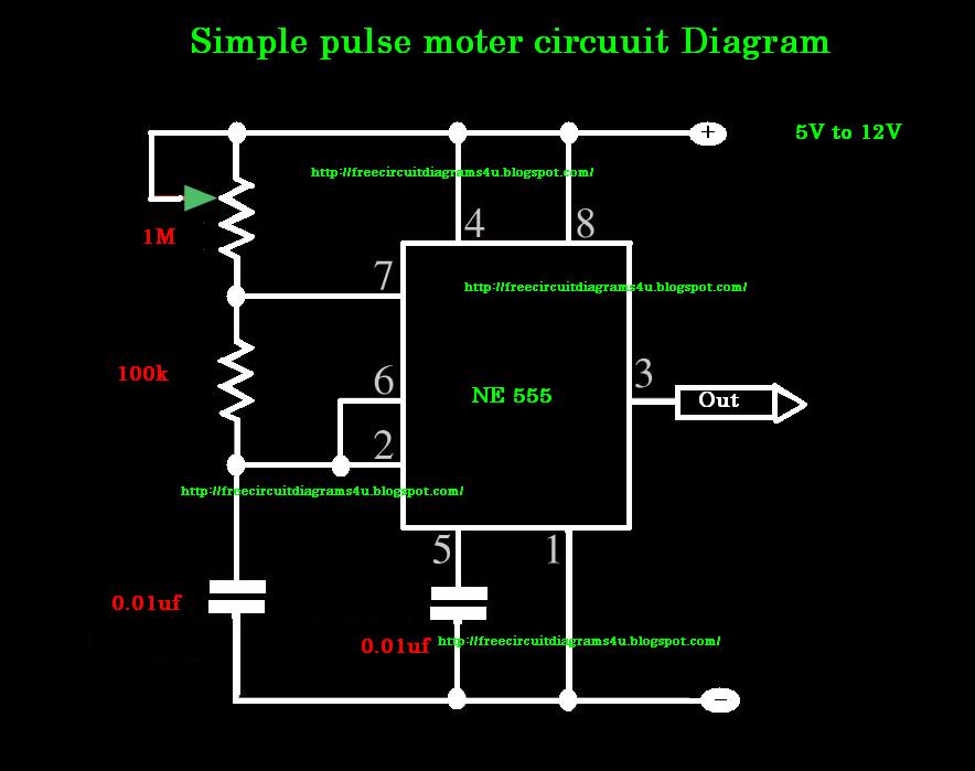
Pulse moter circuit diagram | CIRCUIT DIAGRAMS FREE